GRAPHTEC
Instrument products : DATA LOGGER / RECORDER
GRAPHTEC GL220
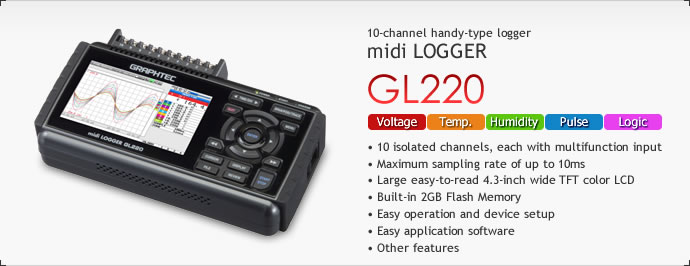
GRAPHTEC GL220
DATA LOGGER / RECORER
![]()
GRAPHTEC GL220 main unit specifications
| Item | Description | |||
|---|---|---|---|---|
| Number of analog input channels | 10 ch | |||
| External input/output | Input *1 | Trigger or Sampling input 1 ch, Logic or Pulse input 4 ch | ||
| Output *1 | Alarm output 4 ch | |||
| Sampling interval | 10 ms to 1 h (in 10ms to 50ms, voltage only and limited channel), External | |||
| Time scale | 1 sec to 24 hour /division | |||
| Trigger function | Action | Start or stop capturing data by the trigger | ||
| Source | Start: Off, Input signal, Alarm, External *1 , Clock, Week or Time | |||
| Stop: Off, Input signal, Alarm, External *1 , Clock, Week or Time | ||||
| Combination | OR or AND condition at the level of signal or edge of signal | |||
| Condition | Analog: Rising, Falling, Window-in, Window-out | |||
| Pulse: Rising, Falling, Window-in, Window-out | ||||
| Logic: Rising or Falling | ||||
| Alarm function | Detecting method | Level or edge of signal | ||
| Condition | Analog: Rising, Falling, Window-in, Window-out | |||
| Pulse: Rising, Falling, Window-in, Window-out | ||||
| Logic: Rising, Falling | ||||
| Alarm output *1 | 4 channels, Output type: Open collector (pull-up resistor 10 kΩ) | |||
| Pulse input function *1 | Accumulating count mode | Accumulating the number of pulses from the start of measurement Range: 50, 500, 5 k, 50 k, 500 k, 5 M, 50 M, 500 M counts/F.S. |
||
| Instant count mode | Counting the number of pulses per sampling interval Range: 50, 500, 5 k, 50 k, 500 k, 5 M, 50 M, 500 M counts/F.S. |
|||
| Rotation count (RPM) mode | Counting the number of pulses per second and then it is converted to RPM Range: 50 rpm, 500 rpm, 5 krpm, 50 krpm, 500 krpm, 5 Mrpm, 50 Mrpm, 500 Mrpm /F.S. |
|||
| Max. input pulse rate | 50 k pulses/sec or 50k counts per sampling interval, 16 bits counter is used | |||
| Calculation function | Between channels | Addition, Subtraction, Multiplication and Division for analog input | ||
| Statistical | Select two calculations from Average, Peak, Max., Min., RMS | |||
| Search function | Search for analog signal levels, values of logic or pulse or alarm point in captured data | |||
| Interface to PC | USB (Full speed) | |||
| Storage device | Built-in Flash memory (2 giga-bytes), USB memory device *2 | |||
| Data saving function | Captured data | Direct saving of data into built-in Flash memory or USB memory device | ||
| Others | Setting conditions, Screen copy | |||
| Ring capturing mode | Function: ON/OFF, Number of capturing point: 1,000 to 2,000,000 (Size of the capture data will be limited to 1/3 of available memory) |
|||
| USB memory device emulation | USB Memory emulation mode (Transfer or delete the file in built-in memory) | |||
| Engineering scale function | Set based on the reference point of the scaled output and input signal for each channel (Voltage measurement: four points are necessary to scale the output, Temperature measurement: two points are necessary to scale the output). | |||
| Display | Size | 4.3 inch TFT color LCD (WQVGA: 480 x 272 dots) | ||
| Formats | Waveform + Digital, Waveform only, Calculation + Digital, Expanded digital | |||
| Operating environment | 0 to 45 °C, 5 to 85 %RH (When operating with battery pack 0 to 40 °C, charging battery 15 to 35 °C) |
|||
| Power source | AC adapter (100 to 240 V, 50/60 Hz), DC power (8.5 to 24 V DC, max. 26.4 V) *3 , Battery pack *3 |
|||
| Power consumption | 29 VA or lower (when operating with AC adapter, displaying LCD) | |||
| External dimensions (W×D×H) | approx. 194 x 117 x 42 mm | |||
| Weight | approx. 520 g (Excluding AC adapter and battery pack) | |||
- *1
- Logic alarm cable (B-513) option is required.
Input signal of External sampling, Logic, Pulse; Maximum voltage: 24 V, Threshold: approx. 2.5 V, Hysteresis: approx. 0.5 V. - *2
- Size of the USB memory device is unlimited. Maximum file size is limited to 2GB.
- *3
- DC drive cable (B-514) or battery pack (B-517) option is required.
Analog input specifications
| Item | Description | |||
|---|---|---|---|---|
| Type of input terminal | Screw terminal (M3 screw) | |||
| Input method | Scans by the photo-MOS-relay, all channels isolated, balanced input | |||
| Measurement range | Voltage | 20, 50, 100, 200, 500 mV, 1, 2, 5, 10, 20, 50 V, and 1-5 V /F.S. | ||
| Temperature | Thermocouple: K, J, E, T, R, S, B, N, and W (WRe5-26) | |||
| Humidity | 0 to 100% (using humidity sensor (B-530 optional), power is supplied to only one sensor) | |||
| Filter | Off, 2, 5, 10, 20, 40 (moving average in selected number) | |||
| Measurement accuracy *4 | Voltage | 0.1 % of F.S. | ||
| Temperature | Thermocouple | Measurement range | Measurement Accuracy | |
| R/S | 0 °C ≤ TS ≤ 100 °C 100 °C < TS ≤ 300 °C R: 300 °C < TS ≤ 1600 °C S: 300 °C < TS ≤ 1760 °C |
± 5.2 °C ± 3.0 °C ± (0.05 % of reading + 2.0 °C) ± (0.05 % of reading + 2.0 °C) |
||
| B | 400 °C ≤ TS ≤ 600 °C 600 °C < TS ≤ 1820 °C |
± 3.5 °C ± (0.05 % of reading + 2.0 °C) |
||
| K | -200 °C ≤ TS ≤ -100 °C -100 °C < TS ≤ 1370 °C |
± (0.05 % of reading + 2.0 °C) ± (0.05 % of reading + 1.0 °C) |
||
| E | -200 °C ≤ TS ≤ -100 °C -100 °C < TS ≤ 800 °C |
± (0.05 % of reading + 2.0 °C) ± (0.05 % of reading + 1.0 °C) |
||
| T | -200 °C ≤ TS ≤ -100 °C -100 °C < TS ≤ 400 °C |
± (0.1 % of reading + 1.5 °C) ± (0.1 % of reading + 0.5 °C) |
||
| J | -200 °C ≤ TS ≤ -100 °C -100 °C < TS ≤ 100 °C 100 °C < TS ≤ 1100 °C |
± 2.7 °C ± 1.7 °C ± (0.05 % of reading + 1.0 °C) |
||
| N | 0 °C ≤ TS ≤ 1300 °C | ± (0.1 % of reading + 1.0 °C) | ||
| W | 0 °C ≤ TS ≤ 2000 °C | ± (0.1 % of reading + 1.5 °C) | ||
| Reference Junction Compensation (R.J.C.): ±0.5 °C | ||||
| A/D converter | ΣΔ type, 16 bits (effective resolution: 1/40,000 of measuring full range) | |||
| Maximum input voltage | Between + / – terminal | 60 V p-p | ||
| Between channels | 60 V p-p | |||
| Between channel / GND | 60 V p-p | |||
| Withstand voltage | Between channels | 350 V p-p (1 minute) | ||
| Between channel(-)/ GND | 350 V p-p (1 minute) | |||
- *4
- Subject to the following conditions;
• Room Temperature is 23°C ±5°C.
• When 30 minute or more have elapsed after power was turned on.
• Filter is set to 10.
• Sampling rate is set to 1s with 10 channels.
• GND terminal is connected to the ground.
Software specifications
| Item | Description |
|---|---|
| Supported OS | Windows XP / Vista / 7 (32 bits and 64 bits edition) |
| Functions | Control GL220, Real-time data capture, Replay data, Data format conversion |
| GL220 settings control | Input settings, Memory settings, Alarm settings, Trigger settings |
| Captured data | Transfers data in real-time (in binary or CSV format), saved data in GL220 or the USB memory |
| Displayed information | Analog waveforms, Logic waveforms, Pulse waveforms, Digital values |
| Display modes | Y-T waveforms, Digital values, Report, X-Y graph (specified period of data, data replay only) |
| Warning functions | Sends E-mail to the specified address when the alarm occurred |
| File format conversions | Converts the specified period data or all data to the CSV format (thinning function is available) |
| Report functions | Creates a daily or monthly report automatically (can also export directly to Excel) |
| Displayed Max. Min. | Displays the maximum, minimum and current value in measurement |
Standard accessories
| Item | Description | Quantity |
|---|---|---|
| AC adapter | 100 to 240 V AC, 50 / 60 Hz (with specified type of power cord) | 1 set |
| CD-ROM | User’s manual (PDF format), Application software | 1 piece |
| Quick Start Guide | 1 copy |
![]()
| Item | Model number | Remarks |
|---|---|---|
| Logic alarm cable | B-513 | 2 m long (no clip on end of cable) |
| DC drive cable | B-514 | 2 m long (no clip on end of cable) |
| Battery pack | B-517 | 1 piece (7.4 V 2200 mAh, 17Wh) |
| Humidity sensor* | B-530 | 3 m long (with power plug) |
| Battery pack (B-517)  |
Logic alarm cable (B-513)  |
DC drive cable (B-514)  |
Humidity sensor (B-530)  |
- *
- Operating environment: -25 °C to 80 °C